LMX4644TSH داتا شيت تحليل عميق: المواصفات، الحدود والرسوم البيانية
Datasheet graphs and limits define the usable performance envelope for thermal behavior, current capability, and efficiency. This deep dive translates those figures into concrete design checks engineers can apply today using the LMX4644TSH datasheet.
Product overview & quick spec snapshot
What LMX4644TSH is and target applications
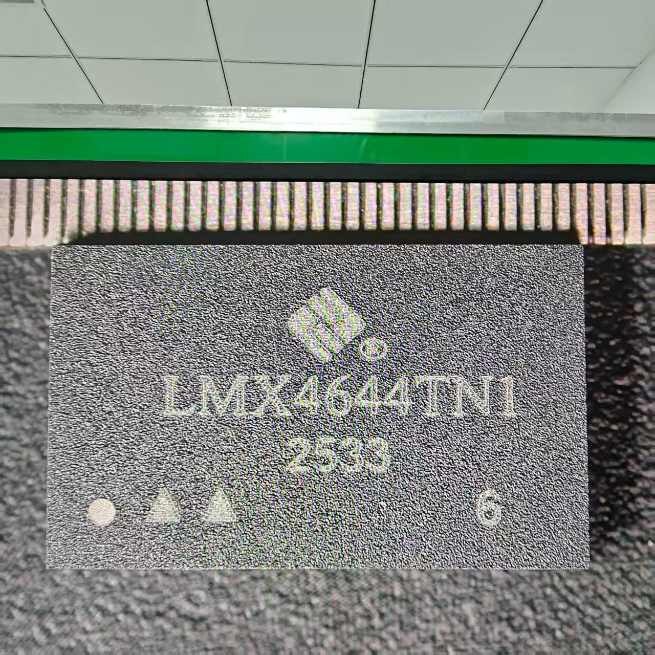
The LMX4644TSH is a compact multi-output power stage intended for point-of-load regulation in high-density systems like telecom, compute rails, or FPGA supplies. Designers must align topology and thermal strategy with these specific application requirements.
| Parameter | Value / Limit | Unit |
|---|---|---|
| Input Voltage (Vin) Range | 4.5 to 16.0 | V |
| Max Continuous Current | 4.0 (Per Channel) | A |
| Switching Frequency | 200 to 1200 | kHz |
| Operating Junction Temp | -40 to +125 | °C |
Electrical limits: absolute max vs recommended operating
Interpreting absolute maximum ratings
Absolute maximums mark irreversible-damage boundaries. Treat these as avoidance zones and design clamping strategies so the board never approaches these spec limits under transient stress or fault conditions.
Recommended operating conditions and derating
Apply a rule-of-thumb derating: reserve 20% headroom for continuous operation and increase to 30–40% for high-temperature enclosures to ensure long-term reliability beyond the minimum datasheet specs.
Performance charts decoded
Efficiency & Thermal Response
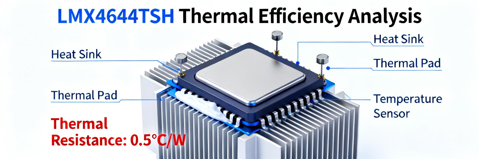
Efficiency vs load curves reveal where the device spends power. Use these curves to size upstream power and heat sinking. Thermal curves determine safe continuous currents; translate these into copper area and via count during the layout phase.
Application examples & layout best practices
For high-current single outputs, prioritize heavy copper and via arrays. For multi-output designs, balance shared input filtering and per-rail decoupling while checking cross-load transient specs in the LMX4644TSH documentation.
Summary
Reading the LMX4644TSH datasheet correctly turns charts into actionable design margins. Replicate core published charts in the lab, then iterate layout based on measured thermal behavior to converge on a validated design.
Key summary
- Translate efficiency plots into board-level loss numbers for realistic thermal budget planning.
- Apply 20% derating to recommended operating values for reliable continuous operation.
- Reproduce datasheet test setups precisely—matching input filtering and probe placement.
Frequently Asked Questions
How do I use the LMX4644TSH datasheet to size thermal vias?
Calculate required junction temperature delta, convert to needed thermal resistance, then determine via count and copper area per standard thermal conduction formulas provided in the thermal management section.
What spec limits should I check first in the LMX4644TSH datasheet?
Prioritize input voltage headroom, continuous output current, and thermal derating curves. Verify worst-case Vin and load current are within recommended conditions with derating applied.
How can I reproduce LMX4644TSH datasheet results in my lab reliably?
Build the recommended bench circuit, use Kelvin sensing, minimize probe ground loops, and use equivalent decoupling capacitors to avoid misinterpreting ringing or rise-time artifacts.
What is the impact of switching frequency on LMX4644TSH efficiency?
Higher frequencies reduce inductor size but increase switching losses. Consult the efficiency vs. frequency charts to find the optimal balance for your specific thermal and space constraints.